
Basic Installation Instructions
Printable Version 
The following instructions will guide you through the basic installation of your Car Vision® Mobile Video Safety System. Your installation may vary. Please contact INTEC for specific questions or recommendations on your application that are not answered below.
DISCLAIMER: Please read and understand all the instructions below and become familiar with your system before attempting any installation. In addition you should be familiar with your vehicle and have basic electrical and automotive knowledge. If you are not comfortable with modifying your vehicle or working around electricity you should refer to an installation specialist. Always use caution when working near electricity.
These instructions cover only the VERY basic installation. While we've made every effort to insure that the information contained herein is accurate we cannot be held responsible for any errors or damage that may occur during your installation.
The tools required will vary depending on your vehicle and application however the basic tools you will need include:
- #2 Phillips Screw Driver
- Metric Socket Set
- Drill & Drill Bits
- Hole Saws
- Wire Cutters and Wire Strippers
- Basic System Wiring Diagram (Included with your Car Vision® Controller)
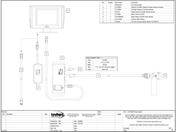
Single camera system wiring diagram.
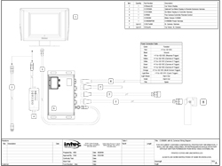
Multi camera system wiring diagram.
Display, Remote and Controller Installation
Before you begin the installation, set the parking brake and disconnect or turn off the battery to prevent accidental short circuits.
The display should be mounted where it is easily viewed and accessible to the driver but not in an area that may block or impede the drivers and/or passengers air bags or forward view. For a dual drive vehicle, the display and remote should be placed where they are accessible from both the left and right side driving position. (An optional swivel base is available.) The display should also be mounted in a fashion that would prevent glare from sunlight affecting the image seen on the screen. It can also be easily flush mounted into a cut out in the dash or overhead console. Generally, overhead center is a good location, but you should determine what location is best for your particular installation. Positioning the display within the normal forward to side mirrors scan line is generally appreciated by drivers. Do not obstruct forward visibility.
Prior to installation, make sure the display does not block the driver's forward or side view in any way.
1. Locate the area in the cab that best accommodates the driver and the application. You will want to make sure the location chosen is adequate to support the display (a metal surface is recommended). In cases where the mounting surface is plastic, support braces may be required.
2. Install the mounting bracket supplied with the display. Use the bracket as a template for drilling the required holes. When a swivel base is required, use it as your template. Be sure to verify that the area being drilled into is cleared of all wires and other items around or underneath so as not to cause damage.
Note: Various optional mounting brackets are available if the standard bracket does not suit your applications.
3. After the holes have been drilled, mount the bracket with the hardware provided. In some cases, the hardware provided may not work in your application and you may need to purchase additional appropriate hardware.
4. Connect the CVDC6MA display to controller cable (included with your controller) and remote control to the display. The cables are labeled at each end and specify what they connect to. An optional display to remote cable extension (CVDR5MA) is available.
5. Secure the display in the bracket with the mounting knobs provided. Refer to your displays Quick Installation Guide for additional information.
6. Mount the remote so that it is easily accessible to the driver. The remote comes equipped with a 1 meter pigtail. For installations that require the remote to be installed further away from the display than the pigtail allows an optional remote extension harness is available as noted above.
7. Install the controller. The controller may be installed anywhere within the cab or outside the vehicle, provided you stay within the available length (6 meters) of the display to controller cable. (Installation outside requires the H or XL series controllers. Do NOT install the M series controllers where they will be exposed to the environment.)
When selecting a location, make sure you have a solid mounting surface away from any source of significant heat or moving parts. Also insure that the controller will not come in contact with any of the vehicle’s electrical circuits; as shorting to the controller’s metal enclosure can occur.
Securely fasten the controller with the hardware provided.
8. Route the display to controller cable to your controller and connect it.
Connecting Power to the Controller
1. Connect the red wire to a post ignition +11 to +32 VDC power source.
2. Connect the black wire to solid chassis ground.
3. Connect the blue wire to the reverse circuit or some other +11 to +32 VDC circuit that is only active when the vehicle is put into reverse. When connected properly, this allows the system to come on automatically and display the OSD distance grid when the vehicle is placed in reverse.
For multi camera applications using the CVS500 Series controllers additional trigger wires are available to activate all other camera positions as well as a programmable multi-screen and dwell cycle function. These triggers follow a priority sequence shown on the Quick Installation Guide provided with your controller.
Cable Installation
INTEC cables are directional, meaning they must be installed one way. The cables are typically labeled FRONT and REAR or to the product they connect (for example: DISPLAY or CONTROLLER). The end labeled FRONT is meant to be installed towards the cab in general, specifically the controller. The end labeled REAR is meant to be installed at or towards the camera.
It is recommended that you start at the front by plugging the cable into the controller and working towards the camera. Keep in mind that most installations will have some cable left over that will need to be coiled up and secured. If additional cable is required short extensions are available for most cable types.
Note: Be familiar with all the pivot points on the vehicle prior to routing the cable. Take appropriate steps to insure long term adequate protection from pinching or crushing the cable.
The following are general tips and precautions to keep in mind while routing the cable between the camera and controller or the controller and display. With the exception of Molex connectors (found on the CVU and CVXLP series cable harnesses), the entire cable is weatherproof and can withstand exposure to cold (down to -40 degrees F), rain, snow, dirt, etc. If you feel the environment in which the cable is exposed is extremely harsh, you can route the cable through a conduit or consult INTEC about our optional application cable harnesses for extreme temperature or environmentally challenging applications.
If exposed to the environment, the Molex connectors must be weatherproofed. A simple means is to use 1-inch diameter adhesive interior heat shrink tubing (Part# CVST10 available from INTEC) to cover the whole connector assembly. This will seal and protect the connector from direct moisture due to rain, snow, vehicle washing, etc. Weatherproof junction boxes, properly sealed, are another means. One should occasionally check the seals to make sure they remain intact. We recommend using the waterproof XL or H cables and connectors so that heat shrinking is not necessary.
DO NOT use electrical tape, slotted plastic conduit or silicon only as a weatherproofing. They may protect the connector for a short period of time but will quickly lose their ability to keep moisture away from the connector and pins.
Other cable installation hints include:
1. Do not attach the cable to moving vehicle parts.
2. Keep the cable at least 12 inches away from any significant source of heat.
3. Avoid running the cable along the same side of the chassis as the ABS wiring.
4. Route the cable where it is protected from road debris or overhead hazards.
5. Secure the cable so that vehicle vibration and shock does not loosen it. Tie the cable down approximately every
12 - 18 inches.
Insulated P-clamps are recommended where appropriate.
6. Secure the cable on both sides of a pivot point allowing enough cable to extend fully but not so much as to cause snagging. Run the cable to avoid getting caught in the pivot point.
7. If you have excess cable, do not coil it too tightly; avoid crimping the cable.
8. Do not staple through the cable.
Rear Camera Installation
For optimum field of view, mount the rear camera as high up on the vehicle from ground level as possible and such that the rear-most part of the vehicle will be visible at the bottom of the displayed image. If this is not possible, mount the camera in a fashion that will give the driver the best possible view of the area behind the vehicle while still aligning the rear-most part of the vehicle with the bottom of the display screen as a reference.
1. Establish a solid mounting location in the center of the vehicle using the guidelines above. Make sure that no part of the installation obstructs any lights or any part of the driver's view.
2. Position the camera with the mounting bracket attached in the location where it will be mounted and turn on the system to check the field of view (you may have to reverse the camera’s mounting bracket to obtain the proper angle). Be certain the field of view of all installed cameras provides adequate and appropriate coverage for your application.
3. Once the location and angle have been determined, use the camera bracket or bracket extension as a template to mark the position where the holes will be drilled and drill the holes. Make sure the area being drilled into is clear of all wires and other items before you begin drilling.
4. Once the holes are drilled, install the camera mounting bracket and extension, if required, with the mounting bolts provided. You may need to purchase additional hardware if the hardware provided does not work in your application.
5. Mount the camera in the bracket with the hardware provided and align it so that the rear-most part of the vehicle is in line and visible at the bottom of the display screen.
6. It is recommended that you apply an anti-galvanic compound to the camera mounting bolts before installation.
Installation of additional cameras follows the same general guidelines as above by first determining where you want to mount the camera to give you the optimum appropriate view for the area you want to see.
Heavy Equipment
Installation of the camera system on your heavy equipment follows the same basic principles as the installation above. See the preceding installation instructions for details.
CAUTION: Read and understand your vehicle's information pertaining to all Roll over Protective Structures (ROPS). DO NOT drill into, weld onto, or modify in anyway any ROPS without written permission from the original equipment manufacturer or an authorized dealer.